Electrician School: Parallel Circuits

Series and parallel circuits are the simplest and most common ways to connect the components in an electronic or electrical circuit.
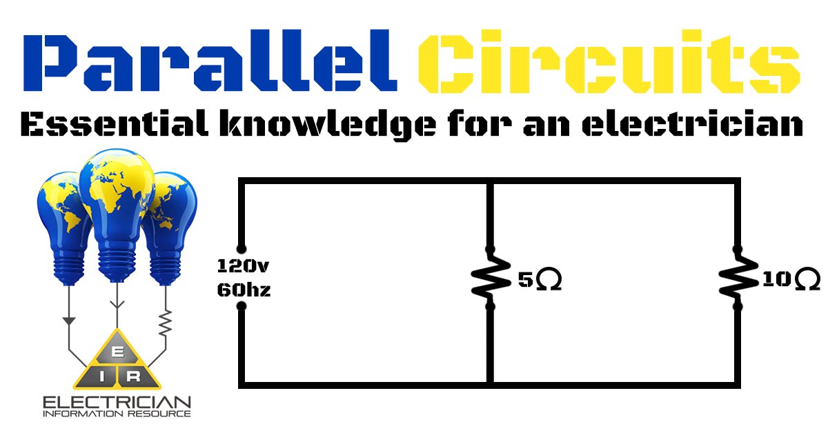
A series is when components are connected in a single path and have the same current flowing through all of the components. In a parallel circuit, the components are connected in such a way as to apply the same voltage to each component.
In a series circuit, each of the components have the same current flowing through them, and the voltage is the total of all of the voltages across each of the components. In a circuit that is parallel, the current is the total of the currents running through each of the components and the voltage across each of the components is the same.
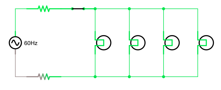
For example, four light bulbs and one 6V battery would be a simple circuit. If one wire joined the battery to each of the bulbs in a row and then came back to the battery, in one unbroken loop, the bulbs would form a series circuit. If each bulb was wired to the battery creating its own loop, the bulbs would be in parallel.
The four bulbs joined in a series have the same current running through all of them, and the drop in voltage will be 1.5V for each bulb, which means there may not be enough power to make the bulbs light up.
With the four bulbs joined in a parallel circuit, the current flowing through each of the light bulbs will combine to form the current in the battery, and the drop in voltage will be 6.0V across each bulb, meaning all the bulbs will light up.
In a series circuit, each of the bulbs in the series must function in order for the circuit to be complete. If one of the bulbs is burned out, the circuit will be broken.
This is not the case with parallel, since each bulb completes its own circuit, so even if all but one light bulb is burned out, the last one will still work.
Series vs. Parallel Circuits

Parallel are different from series circuits in two main ways: In parallel circuits, there are more pathways in the system, and the components of a circuit wired in parallel are lined up differently than the ones in a series circuit. This alignment is what affects the amount of current flowing through the circuit.
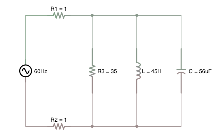
Parallel circuits looks similar to a multi-laned highway, with several pathways running parallel to one another, with each pathway having its own resistor. The current flowing through the circuit splits and some of the current is sent along each of the pathways.
Adding more resistors to a parallel wired circuit will result in less overall resistance. Because there are several pathways in which the current can flow, adding another resistor provides an additional pathway. That means that by decreasing the resistance with additional pathways, the rate of the current will increase.
Think of it like a tollbooth on a highway. The tollbooth is resistance to the flow of cars on the highway. Adding more tollbooths for the cars to flow through, will decrease the resistance and increase the rate at which the cars pass.
Current
The speed at which a charge flows through a circuit is called a current. The charge doesn’t pile up and start accumulating at any one point, so there is never more current at one point than another. The charge also doesn’t get used by the resistors, so there is never less current at any one point.
In a parallel circuit, the charge is divided into pathways, therefore there can be more current in one area than another. Nevertheless, as a whole, the total amount of current in all of the pathways added together is the same as the amount of current outside of the pathways. It is still true that current is everywhere, just in this case, the current is split up throughout the pathways.
The rate at which the current flows into a node is equal to the total amount of the rates flowing through the individual pathways. An ammeter is used to measure the rate of the current.
For example: if a circuit has two resistors and a flow rate of 6 amps, some of the current (2 amps) will flow through one path and the rest (4 amps) through another. When the pathways meet up, the current will once again be 6 amps.
The Advantages of Parallel Over Series Circuits

When you want to use one battery to power two bulbs the obvious way would be to connect them in a series. However, the problem with this is that neither bulb will shine too bright and if one bulb is turned off, they both go off.
When you connect the bulbs using a parallel configuration each gets the full voltage from the battery, making them both bright and since they each have their own loop, you can turn off one without affecting the other.
The appliances in your home are wired in parallel. This means each one gets full voltage and you can use one without turning on everything.
This wraps things up for parallel circuits, learn more at our basic electrical circuits section.


