
Understanding Electrical Symbols
What are electrical symbols, and why are they important to all electricians?
When installing a new wiring system or repairing an existing one, you will probably use a schematic, which is a detailed drawing (or blueprint) of how the system should look.
Every line and circle in the schematic is a specific symbol. These symbols tell you whether the wires are connected or not, where to put in a toggle or push button switch, where to connect a ground, and everything else you need to know in order to install the system correctly.
Electrical Blueprints
Reading blueprints and knowing the meaning of every schematic symbol used is a basic part of your electrician training.
In most cases the electrical symbols used are standard; however, some schematic drawings might use slight variations. It is up to the electrician to properly read and understand all symbols and possible variations used.
When working on an electrical system, the power must be shut off. However, you can use switches and disconnects to turn off the current to certain parts of the system, and keep it on in other sections, which might be necessary when performing various tasks.
The current powers a variety of mechanisms throughout the system, such as motors and controllers. All of this activity has to be clearly outlined on the schematic.
The schematic drawing uses electrical symbols to represent all of the different components within the system.
The Electrical Circuit
The circuit is represented on the schematic drawing. The most basic component in any electrical circuit is the conductor, which is usually a wire.
In a schematic drawing, the standard symbol for a wire is a straight line. When there are two lines crossing over each other without any other symbol, it means the wires are not connected.
If the wires are connected, there will be a dot on the intersection, also called a node. The dot indicates the presence of a connection, and means that at this point current is passing through both wires.
Some schematics will use a semi-circle bridge where the wires intersect, to indicate that the wires are not connected. This is done to make it very clear that the wires are not connected, so there is no chance of confusion.
On average, an electrical schematic depicting a complex system could have as many as sixty standard electrical symbols or more. Each symbol is a representation of a different component within the system.
When there is a component in the system that doesn’t have a corresponding standard schematic symbol, a different symbol may be used. In this case, a key will be included on the drawing to explain the unknown symbol.
Other Symbols
When working on a new building, the blueprints will include other electrical symbols as well.
All of the lights, switches and outlets have their own distinct symbol, so that you know exactly what type of fixture will go where. For example, ceiling lights, recessed ceiling lights and surface fluorescent lights all have a different symbol.
You will also find different symbols showing where to install the thermostat, smoke detectors and doorbell chimes.
What About Colored Schematics?
Colored schematics give you a great advantage over black and white ones when working on complicated wiring systems.
The color of every wire you use is color coded to represent its function.
- Black wires always mean hot wires, which means they have current. This type of wire will be used to feed an outlet or light switch and many other devices. You would never use a black wire as a neutral or to ground a device in any type of connection.
- Red wires also mean hot wires. This type is used to feed switch legs (a ceiling fan for example), and as the second hot wire in a 220-volt installation. Red wires are also useful for interconnecting two smoke detectors in a hardwired system.
- Blue and yellow coated wires are also used as hot wires, and are the ones that are normally pulled in conduit. It is common for blue wires to be used as travelers in three-way switch connections, as well as in switch legs to appliances such as fans and lights. Yellow wires are also commonly used for switch legs. You would install these to control devices such as switched outlets, fans and lights.
- Green coated and bare copper wires act as the ground – only! To avoid confusion, you would never use these in any other applications. These wires bond devices to ground, and must be properly bonded to appliance connections and junction boxes to ensure safety.
Color codes have been known to change over the years, as well are different in some countries, so it is important to always have the most up-to-date information.
It is also important to know the old codes, in case you are working on older wiring systems that may be using old color codes.
Exceptions to the Wire Color Rule
In certain situations, wire colors can be used in applications that don’t fall under these general connection rules.
An example of this is a 240-volt outlet or appliance, where a white wire may be used as the second hot wire in a two-conductor cable.
Another application where you could use a white wire would be in a switch leg for running a three-way switch, or in some lighting applications. However, this white wire must be marked properly to show that it has been connected to serve another purpose, other than as a neutral.
You can do this easily by simply putting black or red electrical tape on the wire. This shows anyone else who may work on the device in the future what the wire is being used for. Also, keep in mind that when you come across a white wire with black or red tape on the end, it is not a neutral.
Further Reading
When you understand electrical symbols and wire colours used on a schematic, and you have a detailed and accurate blueprint, you can make sense of even the most complicated wiring system.
This sums up the electrical symbols article. To learn more, explore the electrician school page.

Recent Articles
-
Electrician Information Resource | How to Become an Electrician & More
Jun 18, 22 02:30 PM
 At Electrician Information Resource you will learn about how to become an electrician, topics covered in electrician trade school, & so much more!
 -
Electrician Training in Montana | Earn Big By Becoming an Electrician
Oct 13, 20 11:08 AM
 Comprehensive guide to electrician training in Montana, types of licenses, job market, wages and career opportunities available for aspiring electricians.
 -
Basic Electrical Theory: Understanding Electricity
Sep 17, 20 10:27 AM
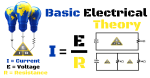 Electrician Information Resource explains basic electrical theory. Learn the basics of what electricity is, and how it works.