
Electrical Bonding and Grounding: The Last Line of Defense in Electrical Safety

At a fundamental level, electricity is simply a difference in energy between two points. Usually, that difference is measured relative to the earth, which is where the term electrical bonding and grounding comes from. In order for the difference in energy, also known as potential, to do useful work for us it generally needs to be kept isolated from ground. Electricity will always take the path of least resistance back to ground, so if the easiest path for it to take is through our motor, heater, light, or anything else we want to power, then our electrical system will continue to operate normally. Given the opportunity though, faults can occur with destructive consequences.
What is Grounding?
Simply put, grounding is the way that parts of an electrical circuit or system are connected to the earth. Grounding includes any grounding conductors, grounding electrodes, and the connections used to securely fasten these parts together. For our circuit protection devices to work properly, the connection to ground must be as low resistance as possible, so grounding electrodes must have as much surface area in contact with the ground as possible. These grounding electrodes can include buried metal water piping, ground rods, ground plates, or bare ground wire grids.
Why is Grounding Important?
Let’s look at an example:
We have a 120V light bulb that draws 1A when operating. When we look at Ohm’s Law (V=IR, or V/I=R), we can see that the resistance of the bulb is 120V/1A, or 120Ω. Now, imagine that a wire has come loose and touched the side of a metal box. There is no longer any resistance from the bulb between the voltage source and ground, so the resistance has gone down to nearly zero. If we re-arrange our formula (I=V/R) and plug in our new resistance (let’s assume 0.001Ω or 1mΩ), we get 120V/0.001Ω = 120,000 A. That is more than enough power to instantly vaporize the copper wire and create a bright flash known as an arc flash. This is why we protect circuits with breakers and fuses, so that in the event of a fault the circuit overcurrent protection device can open the circuit and minimize or reduce the damage in the event of a fault.
Most overcurrent devices function because of heat. When current passes through a conductor, it generates heat. The amount of heat generated is based on the size of the conductor and the amount of current, with more current and smaller conductors generating more heat.
A fuse contains a thin and very precisely sized piece of wire that will melt when a specific amount of current flows through it. When the wire melts, the fuse is considered blown and the circuit is opened. A breaker contains a special strip of conductor made of two different metals known as a bimetallic strip. The different metals expand at different rates when they are heated which causes the strip to flex. When the strip gets too hot, it flexes far enough that it opens the circuit. When a short circuit occurs, the massive inrush of current trips these devices very quickly, which reduces the chance of damage or fire. When the connection to ground has low resistance, the current is high and the devices heat up faster and trip sooner. If the ground connection is poor or loose, there will be more resistance, even during a dead short to ground. There will still be enough current to trip the overcurrent devices, but they will take longer to heat up enough to trip. Until the devices trip, the fault will continue to arc and create enough heat to start a fire, ignite combustible gasses in the area, or injure or kill anyone being shocked by the fault. To prevent this, codes have been written to determine how we can ensure we have created a proper and safe connection to ground.
Now, consider the same example as before, except the box is installed in a wood frame building and the ground wire has come loose. When the live wire touches the metal box, there is no low resistance path to ground, so the breaker doesn’t trip and the entire box is now live. When the homeowner, or even the electrical apprentice, is sent to see why the bulb isn’t working and touches the live metal box, they have created a new path for the current to take, through their body. Depending on several factors such as the type of ladder, footwear, and ground conditions, the unlucky person could get anything from a small shock to a heart-stopping jolt of electricity. This is why grounding is so important; it is the last line of defense in the event of a fault.
Methods of Electrical Grounding
There are a variety of ways to create a good ground connection, and they vary by country, region, and application. The most common types can include ground rods, plates, electrodes, or grids of buried ground wire. Even some non-electrical parts, like buried metal water or gas pipes, can be used as an in-situ grounding electrode in certain situations. To join the grounding conductor to the grounding electrode, special fittings must be used. They may be hydraulic compression fittings, mechanical lugs, or soldered connections. Codes will also state what size and type of conductor to use, and what combination of grounding devices may be used. Large facilities may require a network of grounding devices, wire, grids, and conductors to satisfy code requirements. Always check with your local codes and regulations to ensure that you are installing a safe and code-compliant system.
Circuit Grounding
In some situations, the grounding conductor is also part of the electrical circuit. In single phase power distribution for example, the Earth is used as part of the power circuit, thus eliminating the need for a second wire in the distribution network. The Earth itself becomes the common conductor from the point of utilization back to the power plant or substation. In this case, it is important not only to have a secure and low resistance path to ground, but to also protect the grounding conductor from damage, especially on the high-voltage utility side of the transformer. If that grounding conductor is broken, the live side of the conductor will take the next lowest resistance path to ground which can cause arcing, arc flash, or fire.
Impedance Grounding
Up to this point, the goal has been to have a low resistance, or impedance, path to ground. But in some facilities, it might be desired that the plant continues to function even in the event of a minor ground fault. In this case, a neutral grounding resistor or NGR can be used to monitor the facility for ground faults while keeping the system operating until the fault is resolved. This type of system is known as an impedance grounding system because it imposes a set impedance between the earth ground and the facility ground. By monitoring current through the NGR, an automated system can alert facility maintenance crews if it detects a fault without shutting the entire facility down.
To learn more, check out this electrical grounding course.
What is Electrical Bonding?

While grounding and bonding might seem like the same thing, they have some very important differences. Electrical bonding is the practice of connecting metallic objects that may be exposed to electrical faults or induced voltages to the grounding conductor. This ensures that in the event of a fault the current will have a low resistance path to take to trip the overcurrent devices as quickly as possible, as well as providing a path for static electricity and induced voltages to drain out. Bonding conductors must also be sized so that they can safely carry the largest possible load that might occur in a fault condition. Consult your local codes and regulations for how to size these conductors properly.
When is Bonding Required?
Whenever there is the potential for a conductive metal part to become energized, it must be bonded to ground. This includes conduit for wires and cables, raceways and cable trays, and service equipment enclosures and junction boxes. Bonding is also required for non-electrical equipment that is near our electrical system like ventilation ducts, water and gas piping, or stairs and handrails. This is especially important in areas where occupants will be able to come in direct contact with exposed metal parts or areas where there is the potential for explosive gases or dusts to exist. The exact requirements of what you must bond will be listed in your local codes and regulations, but if you are unsure it is generally better to bond it.
Bonding Methods
The most common way to bond is with copper wire. Most electrical boxes will have factory installed bonding terminals or screws that are designed to make bonding quick and easy. You can also use a crimp lug or a mechanical lug and a nut and bolt connection when there are no factory terminals, or they are too small to accept the correct size of wire. When adding non-factory bonding connections, always scrape away any paint or finishes in the area that you will be connecting your bonding conductor. Even a thin layer of paint can increase the resistance of your bonding connection and reduce the effectiveness of the bond in the event of a fault.
In some cases, conductors other than wire can be considered bonding conductors. For example, threaded metal conduit, EMT with compression fittings, and cable tray can be considered bonding conductors in certain situations, while EMT with standard single screw connections cannot. Always check your local codes and regulations to make sure your bonding system is code compliant.
Bonding Jumpers
It is not always necessary to run a continuous wire from the ground to each individual part in a bonding system. In certain conditions, metal parts need only be connected to each other to form a complete bonding system. Typically, panel doors will have a small bonding jumper that bonds the door to the metal backpan or grounding conductor. The sizes of bonding jumpers in panels will typically be specified by the panel manufacturer or by engineered drawings.

In cable tray systems, jumpers are used across swivel joints or expansion joints to ensure that the continuity of the bonding system is maintained. When preparing bonding jumpers for expansion joints, leave an extra bend in the wire or use a flexible bonding jumper to keep a good connection even when the tray expands and contracts. Cable tray can expand several inches in either direction during extreme heat or cold conditions.
Cable Armor Bonding
When using teck cable, the outer aluminum armor of the cable must also be bonded to ground at both ends. Teck cable will include a bare copper wire for this exact purpose. Connect this electrical wire to a ground bushing which will complete the path from the bonding wire to the cable armor.
When installing teck cable into a teck connector, always ensure that the metal ring inside the connector is making good contact with the exposed armor. This metal ring is what makes the connection from the connector body to the armor.

Touch Potential
Another important use for electrical bonding is to reduce touch potential, especially in long runs of conductive cable tray. When voltage is applied to a conductor, be it a wire or anything else metallic, there will be some voltage drop across the length of the conductor based on its size, material, and length. Even highly conductive copper and aluminum has some resistance. Based on the distance from the nearest grounding connection, small differences in potential can occur. If there is a difference between a cable tray and a nearby staircase, someone who touches both metal objects at once might experience a shock. Having more frequent bonding connections will reduce the potential between nearby metallic objects and decrease the chance of unintentional shocks from static or induced voltages.
On large industrial sites that process potentially flammable or explosive fluids or gasses, even a small static shock can be disastrous. Great care must be taken to ensure that bonding connections are secure and frequent enough to minimize the risk of fire or explosion.
Residential swimming pools and fountains can also be susceptible to touch potential differences, especially when water meets metal surfaces. Metal parts of pools, hot tubs, and fountains must be bonded to earth to reduce the risk of shocking anyone who might come in contact with these surfaces, especially when the watery environment increases the chances of providing a path to ground through a person’s body.
Corrosion Protection
Bare metal exposed to the atmosphere will eventually corrode. These corrosive deposits can build up between the bonding conductors and the metal objects they are meant to protect. Always apply corrosion proofing spray to bonding connections to reduce the risk of weakened bonding connections over time.

Another consideration is when dissimilar metals are joined together, especially copper to aluminum. Due to a phenomenon known as galvanic action, metals of different types will tend to corrode and oxidize in the areas where they meet, weakening electrical bonding connections. To prevent this, apply an anti-oxidation compound like Noalox to aluminum surfaces when using copper bonding wire. To learn more about electrical bonding, you can take this online electrical bonding course right now and test your knowledge.
DC Reference Common
While grounding and electrical bonding are typically used for safety reasons, another use for grounding is to provide a common reference point for DC circuits in panels and circuit boards. This common point may be connected to the earth ground, but many electronic devices will mark the common part of the circuitry as “ground” even if the device has no real connection to ground. When using a metallic backpan or ground bar in a panel, all of the negative wire leads can simply be wired to the nearest grounded point instead of being wired individually back to the negative terminal of the DC source. This simplifies wiring and reduces material used in panels.
Shielding and Isolated Ground
Analog signal wires and communication cabling will typically be shielded. This shielding is usually a thin wrap of conductive foil or braided wiring which will protect the wires inside from signal noise from nearby cables or other sources. Shielding acts like a Faraday cage and drains induced currents back to ground without interfering with the signal wires inside.

When working with shielded cables, the common best practice is to bond the shield to ground at a single common point. This reduces the likelihood of ground loops occurring. If two different points are used at either end of a shielded cable, and these two points happen to be at slightly different potentials relative to each other, this difference will flow through the shield and cause interference, noise, and even audible humming on audio cables. Many electricians will have heard the saying “no shield in the field” which simply means that the shields of shielded cables should be isolated from ground at the end devices and bonded to ground at a single point at the main panel or junction box. When splicing shielded wires, the shield wires must also be spliced through but should not be bonded to ground, as this can cause ground loops.
In large facilities, the need to control ground loops and interference is essential. Often, an isolated ground bar will be used specifically for shields. This ground bar is installed on insulating risers to keep it separated from the grounded backpan, and will be grounded to a single point somewhere in the facility. This ground will typically use an identified marking scheme to ensure that only shields are connected to it.
This wraps up this article, we cover a lot of electrical theory topics so feel free to explore more.
Are You Ready To Test Your Knowledge?
Confirm your understanding with this in-depth grounding and bonding article and knowledge testing quiz.

Recent Articles
-
Electrician Information Resource | How to Become an Electrician & More
Jun 18, 22 02:30 PM
 At Electrician Information Resource you will learn about how to become an electrician, topics covered in electrician trade school, & so much more!
 -
Electrician Training in Montana | Earn Big By Becoming an Electrician
Oct 13, 20 11:08 AM
 Comprehensive guide to electrician training in Montana, types of licenses, job market, wages and career opportunities available for aspiring electricians.
 -
Basic Electrical Theory: Understanding Electricity
Sep 17, 20 10:27 AM
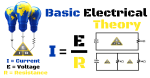 Electrician Information Resource explains basic electrical theory. Learn the basics of what electricity is, and how it works.